When are you ready to start welding? When you’ve prepared the workpiece, the system is switched on, the protective equipment is in place, and the gas hose is already connected? Our blog post provides a step-by-step guide to setting up your MIG/MAG welding machine, including recommendations for practical tools and features that simplify the setup process and save you valuable time.
1) The parent material
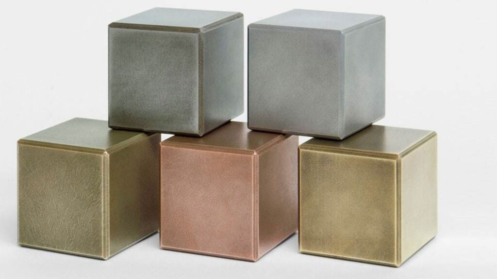
Long before it becomes a question of what welding machine settings need to be applied, it is necessary to identify the metal the workpiece is made of—the basis for all further steps. In most cases, the welder is of course aware of the material in question. If not, some test methods will help:
- Visual impression: The trained eye can see at first glance whether the material is steel, stainless steel, aluminum, or another metal. The color is a particular giveaway. Dull, dark gray indicates a high iron content. Bright and sparkling suggests chrome-nickel alloys.
- Magnet test: In case of doubt, a magnet can help to identify the material. Only steel, nickel, and cobalt are magnetic at room temperature. If the material is strongly attracted to the magnet, it is usually iron or low-alloy steel. If there is a weak attraction between the material and the magnet, it is probably alloyed stainless steel. Aluminum is not magnetic.
- Oxidation: If the workpiece has formed rust spots, it is steel. Stainless steels, also known as chrome steel and aluminum, do not rust.
- Weight: This criterion is particularly relevant with regard to aluminum. Steel has a much higher density than aluminum, and the same size of material is therefore about three times as heavy.
2) The filler metal
Before you can get started, you first need to choose the right wire electrode. The electrode must match the base material and be of higher quality in comparison. This is because during welding, alloying elements in the base material and in the wire electrode evaporate due to the heat. If an equivalent filler metal were to be used, the weld seam would ultimately be inferior and this must be prevented.
3) The shielding gas
MIG/MAG stands for metal active gas or metal inert gas welding. Both are known as Gas metal arc welding. Which process is ultimately used and the choice of shielding gas is also dependent on the base material: steels—from unalloyed to high-alloy—are MAG welded with a mixture of argon and CO2. The MIG process is used for non-ferrous metals such as aluminum or magnesium. Inert gases, i.e., argon and helium and mixtures made from these, are used for this purpose.
4) The gas quantity
Next, the gas valve is opened and the gas quantity is adjusted. There is a practical rule of thumb for this:
Gas quantity (liters/minute) = wire diameter (millimeters) x 10
For example, if a wire electrode with a diameter of one millimeter is used, ten liters per minute are sufficient in a closed workshop. If there is a draft, a little more gas is needed.
5) The grounding cable
Before the welding system is adjusted, the return lead cable must be connected. The clamp should be attached as close as possible to the weld seam. If you’re working on a welding table, the clamp can be mounted on the table, otherwise it must be attached directly to the workpiece.
6) Welder settings
The most important measured variables in MIG/MAG welding are wire speed (in meters per minute), amperage (in amperes), and voltage (in volts). They are always dependent on the thickness of the material and the welding position.
These parameters influence each other and must be in perfect harmony. Modern welding systems have synergetic characteristics (also called “synergic lines”). These are welding programs that adjust the other relevant parameters in the background when you set one of the values on the control panel.
Most often the welding specialist sets the amperage. This is generally around 50 amperes per millimeter of sheet thickness. In the case of increasingly thicker sheet metal, this factor is reduced to 40 or even 30 amperes, because the already high heat input must be reduced.
The welding position also influences this rule of thumb. If, for example, welding is carried out in an upward position, less current is used so that the liquid weld pool does not fall victim to gravity. In addition, the characteristics used must be observed. For example, if you weld with a pulsed arc, there is considerably more heat involved. As a result, the amperage can be significantly reduced. Once you’ve applied the welder settings, you should first test them on a test sheet.
Or simply use an app for your welder settings
Does all that sound too complicated? There is also a digital solution! Welding apps guide you intuitively through the basic information. Base material, filler metal, shielding gas, desired welding speed, weld seam profile, and number of beads simply need to be entered and you’ll receive the basic parameter sets in no time: current, voltage, wire speed, deposition rate, and heat input.
Using the Wizard function of the Fronius WeldConnect app, these parameters can also be transferred directly to the welding machine wirelessly via Bluetooth. The app therefore not only helps to find the right parameters, but also saves time when applying welder settings.
The app is available to download free of charge for iOS in the App Store and for Android in the Google Play Store.
How to precisely apply welder settings on a MIG/MAG welding machine: our solutions
How well a MIG/MAG machine can be set depends not only on expertise, but also on how the machine is operated. This is exactly where Fronius Fortis and TPS/i come in: both systems not only guide you through the individual setup steps, but also assist you during the subsequent welding process with intelligent assistance features that simplify procedures and make your work noticeably more efficient.
Intuitive support with the Fortis
Find the right setting quickly: the Fortis series guides even less experienced users safely through the setup process. The built-in welding parameter wizard guides you step by step through material, process, and requirements—a real advantage in times of a skilled labor shortage. The digital, clearly structured display also enables quick process changes and easy operation via rotary push buttons. Our how-to videos show just how easy it is. Watch now and discover just how simple it is to set up the Fortis.
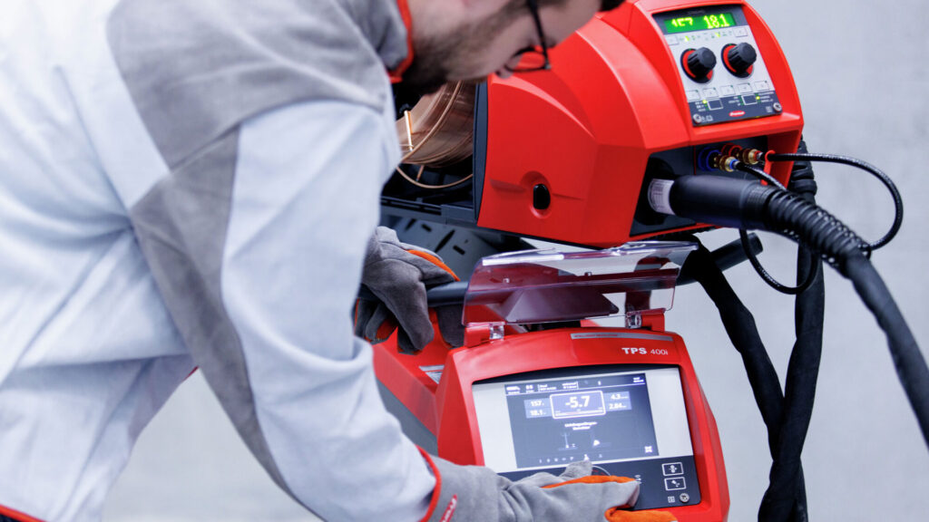
Smart control with the TPS/i
The TPS/i also features an equally intuitive operating concept, enhanced with intelligent functions for more demanding applications. Using the central rotary push button or the 7-inch touchscreen with plain-text display, materials, processes, and parameters can be intuitively selected and precisely adjusted. Graphical guides and dynamic visualizations show in real time how changes affect the system. This way, you can keep track of everything at all times and easily find the optimal setting. Curious to see what else the TPS/i can do? You can find more information, videos and usage tips here.
And the best thing is: thanks to Bluetooth and Wi-Fi, remote control options can be easily integrated into both machines, providing additional flexibility in the workplace.
Get started and see how easy it is to set up your welding machine with modern Fronius solutions!
FAQs on applying welder settings
Checklist: Preparation & setup—what should I check before welding?
- Safety: Personal protective equipment is complete; extraction and ventilation systems have been checked
- Base material/filler metal: Material identified, correct wire electrode selected
- Wire system/wire feeding: Torch properly equipped (inner liner, inlet piece, etc.), hosepack laid out without kinks, contact pressure of the wire feed rollers properly adjusted
- Shielding gas: The correct gas has been selected and the correct gas quantity has been set
- Return lead cable: Clamp attached close to the weld seam
- Parameters: Wire speed, amperage, and voltage are set correctly
Why does my welding machine spatter so much—is it a matter of settings?
In many cases, yes. Welding spatter is often caused by an unstable arc, usually due to incorrectly set parameters, irregular wire feed, or insufficient gas shield. A poor ground connection or incorrect torch positioning can also contribute to spatter formation.
Tip: You can find a collection of practical tips in the article “8 tips to prevent welding spatter”.
What is a reasonable flow rate for shielding gas (l/min)—does the 10× rule of thumb always apply?
The rule of thumb gas quantity (liters/minute) = wire diameter (millimeters) x 10 is a good starting point for calm, sheltered conditions (e.g., a draft-free workshop).
Outdoors, however, the gas shield flow can quickly become restricted—in which case it often helps to increase the gas flow moderately by about 2 to 3 l/min.